
Electrical Outlet Wiring: Practical Tips & Video Tutorial
We put together an easy to follow electrical outlet wiring tutorial which includes practical tips and video resources showing you how to do the job.
Electrics, dangerous, scary and something that should be left only to the professionals right? This seems to be a common perception these days and perhaps rightly so, I mean you may be thinking that one wrong twist of a flex or snip of a wire and you could be in a world of hurt.
It’s a job that requires years of training and complex knowledge to do even the simplest of task like replacing an electrical outlet. Well, we’re here to officially tell you that this mindset is wrong, very wrong. Like many DIY jobs that are a little more complex perhaps than simply painting a wall, there is now a belief that these jobs are untouchable by the average homeowner and should be reserved for the professionals only.
This is harmful not only to the homeowner as it takes away our sense of pride and accomplishment when we do these tasks for ourselves. This may not sound like a big effect but we think it is when you buy a house you want it to be a home, your home for your family and doing these jobs yourself helps you to take control and feel the master of your surroundings.
Safe Isolation Procedure
Before we delve into the real electrical work then we need to first consider the question of where do we actually begin with a job like this? There are after all so many complex parts and steps when it comes to this type of project. Well like any job that is rife with potential hazards and dangers, start by doing all you can to provide a safe working environment for yourself and those around you.
This is done in two similar but sperate ways depending on the type of job you’re actually undertaking. Both options will be tackled separately.
New Build
The new build option is as the name suggests, the procedure you should follow when installing a new electrical outlet box, fascia, and cord, usually this is done on a new build house or possibly in the scenario where you might be building a new partition wall etc.
Either way, this step follows the presumption that you are tracing a new electrical cord all the way back to your panel, a junction box or spurring off an existing outlet. For a new build then the safe insulation procedure is actually fairly straightforward since the cables should not yet be attached into a breaker or any other source of power.
Ensuring it is not connected, tape up the end and label it according to its location and purpose. Make sure the excess is coiled up neatly and not in a position where it can cause any harm or accidentally touch any live terminals.
Once the utility power side is safe, you can now begin to get to work on the socket end. See below for the instructions on how to do this.
Existing Build
The second option is the procedure to follow when you are improving an existing outlet, this might mean changing the fascia because the existing one is broken or old, or you’re adding in a completely new outlet to an existing circuit, this means you’ll need access to the insides of an already installed outlet box so you can continue the circuit on.
When adding on to a pre-existing build, you need to ensure the cords and terminals you’re working with and laying aren’t hot. This is the absolute first stage to any and all electrical work. To do this on an existing outlet, you can easily test it by plugging something into it and turning the appliance on. If there is no power then don’t begin to immediately rip the socket apart to begin work, this is used for indication only and not an approved method of testing an outlet for working purposes.
Next, you need to check the electrical panel to see if the circuit your working on is connected into a circuit breaker and most importantly if the breaker is turned on. If the cable end is NOT connected into a breaker then see the above section, if however, it IS connected into a breaker, even on a new install, you need to ensure that the circuit breaker is isolated then locked off, this guarantees the end you’re working on is not going to come live by accident or by an unknowing bystander turning it back on.
There are several methods and tools to ensure you have the right breaker, one way is to plug in and turn on an appliance, then turning off the breakers one by one, have someone if possible, phone or shout when the appliance powers down.
If you are working by yourself, then you can follow the same method but walk back to see if the appliance is dead or you can use any number of electrical testers and devices that will show you if your device is disconnected.
To ensure your absolute safety after you have turned the breaker off, an isolation lock, like the one below, should be used, this ensures that no one can just come along, see the switch turned off and then turn it back on without realising you are on the other end, this could lead to potentially a very dangerous situation.

Once the circuit is isolated correctly and locked off, you next need to test the outlet to ensure it is definitely not hot.
To do this, we recommend the use first off of an outlet fluke tester like the one below.
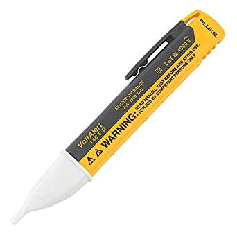
This will again give an indication if a circuit is dead or not by lighting up if there is still electrical flow to the outlet, alternately you can again try an electrical appliance for indication purposes by seeing if it switches on and works or not. Presuming the appliance doesn’t come to life then you should be okay to begin second stage testing.
Second stage testing is carried out because simply trying the outlet to see if it’s dead is not a guaranteed test, for example, the incoming hot cable (black) could still be active but may have come loose from the socket terminal, this would, in turn, give you a false negative reading.
To ensure you are working with a dead circuit then you need to use a multimeter like the one.
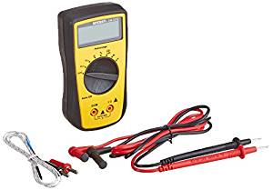
Switch your meter to AC Volts which is designated by the symbol that looks like this: V~ in words this is a capital v followed by a tilde symbol.
You are supplied with two testing cables, one red and one black.
The red goes into the part of the multimeter that tests for the hot connector, on the meter, this is designated by a large V and then an Ohm symbol that measures resistance. This socket is where the red testing lead goes.
The black lead goes into the socket that is labeled COM, which stands for common ground.
With all leads connected, multimeter on the right setting and your initial isolation done you’re ready to test the outlet to see if it’s hot or not.
To do this insert the black lead into the ground slot which is the more circular hole located underneath the two slotted holes.
Now using the red testing lead push it into the smaller top right slot, this is always the hot side. On your meter, you should see a reading of 0.00 volts. There may be a number like 0.06 or some other very low readout, this is what we call stray voltage in the air or cables, it’s not to be worried about and does not mean that the supply cords are hot.
If you get a reading of 0.00 then move the black cable to the top left, or neutral slot, now retest the same way and again you should see a voltage of 0.00 or somewhere therearound.
If the reading is 120.0 or something in that region it means the lines are hot and you’ve isolated the wrong circuit, US utility power runs at 120volts just for reference and that is why your meter will read at 120.0.
Repeat the above process until all reading is at zero. Now you can gently unscrew the front of the outlet to gain access to the inside terminals where the supply cord feeds the outlet. Once you have access to the terminals you need to check and make sure that the incoming supply is securely attached to the terminals and now retest them in the same way you did the front, use the red and black leads directly on the incoming supply terminals and check again for your 0.00 reading.
Once you have this you know for a fact your incoming supply is no longer hot and the real work begins. That is the actual installation so see below for both fresh installation guides and how you go about changing or extending an existing circuit.
New Build and Extention Installation
For both a new build installation and adding an extension to an existing socket, this process will more or less be the same. The only difference is your incoming supply cord will be either spurred off of an existing socket or linked directly back to your supply panel or junction box.
The new build side requires certain standards and regulations to be followed however when dealing with things like pins on the flex and backbox height requirements. These I intend to give a description of as it follows nicely with actually attaching the cord to the outlet fascia.
Now there is one critical and easy way to ensure a safe working environment under both circumstances of new build flex laying, that is to avoid connecting the end of the cord that will provide the incoming supply from the pre-existing mains power supply. It doesn’t really matter too much if this supply is coming from a junction box, existing outlet box or a breaker from a supply panel, leave enough cord-free or better still unravel the spool from the end you about connect and work backward.
This method ensures the end you’re connecting is and will stay cold.
Knowing your safe working practices and having put them to use, it’s now time to begin the serious work of installation. We have to mention that this is a reference guide only uses the most standard or common practices for things like measurements and cable sizes. It is worth knowing and finding out your local state requirements as they may vary from this guide. To do so, the easiest way will be to ask in your local hardware or electrical supply stores. Alternate to that you could search online to find out.
The easy to follow guide starts here then, again remember to check these measurements and sizes against local state requirements.
The first thing we are going to have to do then is to embed the electrical outlet backbox into the wall. This box should be approximately twelve inches off a finished floor. Supposing you are lacking a measuring implement or are wanting to work a little faster than making each measurement exact then a great tool for reference is your hammer. Providing you have a standard 16oz hammer, then it is likely 13 inches long.
A simple way to check this is to measure your hammer once before you start work, if it is the right length then you know you can use it for each box to accurately predict the same and right height.
By placing your hammer on an unsurfaced/finished floor then placing the box on top and securing it at that height, by the time you have laid a flooring the back box will be around your twelve-inch mark. The hammer linked below is the type you should be after and the right length, using a reference like this, especially when working with stud walling will work great, simply place your backbox on top of the hammer when it is facing upright off a floor, then hammer or screw the backbox in.

If you repeat this with multiple back boxes then you will be accurate enough with your measurements.
Remember that when you are working with electrics and flammable materials then every precaution should be taken to ensure long-term safety. When securing a backbox to a wooden drywall section then consider using a type of tape, under some state law this may be a requirement, this helps to isolate the back box from the wooden post.
For already surface finished drywall sheets and stone walls then a new hole will need to be cut, for stone, a hammer and chisel will be needed and for drywall, you will need to drill a small hole then cut out the shape for the back box, keep in mind you also need to lay the supply cord.
This can be done by making a series of smaller holes and threading it through by hand or with a cord threader, do this until you are able to tap into a junction box or simply cutting a long channel all the way back to your supply mains is the other option. This part really depends on the age, layout, and design of your home so I can’t offer to much advice here sadly other than figure out your wall material and locations then proceed with the best method that most suits your individual circumstance.
Once you have located you backbox and secured it to your wall then it’s time to lay some cords. If this is a single spur, so you have an incoming supply and that’s it then you shouldn’t need to knock out more than one of the ‘punch outs’. Use your hammer and a screwdriver to break these out.
Once removed you need to thread in the cord ready for making the connections. To ensure you have enough excess cord I advise feeding through about eight inches.
The cable type again depends on local area code but also on the location of the box and outlet.
For a commonly used and widely accepted cord size for a standard room to room connection and general indoor wiring use a 14/2 cable size. For a bathroom and kitchen use 12/2.
So at this point, we have our wall sorted, back box fixed and the flex eight inches of excess flex coming out the box. Now we need to secure the flex to the wall or stud wall. To do so we advise fixing a hammer in staple within 12 inches of the outlet box. This will also fall in line with a lot of state codes, even in states where this is not a requirement we advise securing your incoming supply with a staple anyway as this helps to stop any excess movement in the flex. When hammering in the staple, ensure the cable is flat against the wood or surface, any twist will be a breach of code as the inner core may become damaged.
Next then comes the actual connection work and this is where there are varying debates around the methods. The most common tool to be used is the utility knife of ‘Stanley’ to call it by it a common trade name. This can be used for all parts of stripping and prepping the cable but the problem arises from the lack of control, for example, the next step is to remove the outer sheathing of the flex to reveal the inside cores. The issue here is if you score and cut through any of the inner core sheathings then the flex is no longer structurally sound so to speak and will need replacing, there are specialist tools available like the one below.

The tool linked won’t work as stripping the outer sheathing but alternative tools can be found, that works in a similar way to a knife. The debate really arises from the safety side vs common practice, as long as you are very careful and check all cuts then you can get away with a knife, we can’t recommend this but it should you choose to then be aware of the risks.
For argument’s sake, we are going to take it from the point of view of using a knife.
Once the outer sheath is cut, use the knife to chop through the end of the flex. Now peel both sides of the slit apart and pull the sheath the opposite way to where you made the slit, do this while pulling the inner cores along the line of the slit, this will then pull apart all that’s needed with relative ease.
Once done you need to chop off the loose outer sheathing and any inside loose paper supports, do this close to the hole in the back box and leave about half an inch or so excess to provide protection against any sharp corners. You should be left with three wires, one with black sheathing, one with white and a single, uninsulated core.
With the exposed wiring you need to next prepare the ends for connection, this is done at about six inches from the point of the incision in the backbox.
Cut the wires to the same length, then using the wire stripping tool, use the relevant gauge, so 14 or 12, strip the wire of about half an inch or insulation. Now fold the wires over neatly into the backbox following a zigzag pattern and you’re ready to move on.
At this stage, if you are installing drywall or doing any other repairs or major work to hide the flex cords then do this now, run the cable back to your supply but do not connect it yet. Once complete you are ready to connect the wires to the electrical outlet.
The first stage of the connection is to take some long nosed pliers and fold over the exposed end of the cables into a loop. This is essential for ensuring a secure connection.
Just before you do secure your wires to the socket connections you need to note if there are any exposed wood or other flammable material between the recessed electrical back box and the fascia. If so then this is a major health and safety concern. You should use a plastic extension box to fill the void. This will provide a fire resistant covering between the electric cables and the front. Not doing so will mean your installation is at risk of fault and fire, which in turn is a breach of the electrical codes.
Once the spaces are filled, you should be ready to make the connections. For a standard fifteen amp plug, there are two brass screws on one side, two silver screws on the other with a green screw at the bottom to connect the ground.
For the first part of the installation then, you need to loosen one of the brass screws, then hook the looped black cable over or through the brass screw making sure you tighten it towards the open end of the core, where you cut it.
Now turn the socket over and loosen one of the silver colored screws and connect the white wire the same way, make sure again you tighten towards to open end.
Now finish off by connecting the bare copper ground wire to the green screw.
Make sure all the connections are tight with no loose movement at all. A loose connection could cause arcing and carries a risk of an electrical fire. Also please take into consideration that the temptation might be there to not bother with creating a hook and instead just to cut the core, place it under the screw and tighten. This is a common practice for untrained professionals but one I advise you avoid. Doing so runs a very real risk that a connection may come loose which could cause a whole range of potential dangers including fire, electric shock, false isolation readings and more.
Once the connections are made and secured you need to then fold the wires back into the connection box in your zigzag pattern and screw the front outlet fascia to the backbox, this is done by two long, silver screws that should already be attached to your outlet.
Just a final note, if you are going to attach another spur onto this new outlet, or when connecting to an old one, there is generally more than one screw on each connection to ensure you have room for expansion and multiple connections.
For plastic back boxes, you need to ensure you attach the ground wire to your front connector, for metal back boxes, we advise you do the same, we know it can be common practice to not because the back box is metal and grounded but the more protection you have, the better and in terms of electrical matters, the more the better.
Where there are options available to protect yourself and other you should always take them.
Existing Outlet Upgrade
Working on an existing outlet fascia is a lot simpler task than installing from new. All you’re doing is taking the existing fixture, safely isolating it then replacing it for something newer. This could be because the existing outlet is old, damaged or installed incorrectly.
To do this then, you need to first carry out your safe isolation procedure first.
Now you need to unscrew the outlet from the backbox and pull it away just enough until you can see where the existing cables fit into the outlet. Unscrew them while trying to keep the socket front in the same position so you’re not bending of moving the cables too much. This is helpful for several reasons, the main one being that the locations for the cables from the old outlet terminals should actually be the same as the new replacement part. To check this, once the old outlet is detached you can hold it against the new one to double check.
Before reattaching the existing cords you need to first ensure they are still fit for purpose. To be certain of this, a simple visual check is all that’s required. What you need to look for are signs of scorching or black burn marks where there may have been a loose contact causing an electrical arc. Also, check that the cable insulation is still flexible and not brittle or old and broken. If it is, then you may find the new build section useful on how to replace an existing cable with new. Also, you should consider the last time your home has its entire electrical system upgraded.
It’s estimated that there are around 26,000 fires a year in the US that are attributed to electrical causes, primarily being old and decaying systems.
It is recommended that you should have your homes professionally tested every 5-10 years, especially for homes that are more than 25+ years old.
This will help to check for old and decaying cables, short circuits and loose connections that could all cause a lot of harm and/or damage.
This work should ideally be carried out by a certified electrician so you can have the proper documentation post-testing. Depending on the result you’ll ideally be fine for another 5+ years before another test is needed. If the results are not so good then you may need at best a circuit or two replaced, at worst an entire home rewire. For a complete home, you are looking at paying between $8,000 to £15,000 for a space averaging around 3000 square feet.
Presuming you have checked the existing quality and are happy to proceed with the existing cords, you can attach the new socket front. Starting with the incoming hot core which is color coded black, you can screw it to the relevant connector. Now attach the ground which is bare copper or green and then finally, secure the neutral which is white.
These cords should already have a looped end from the previous connection, if not use long-nosed pliers to make them. Not hook the loop around the screw and tighten towards the open end.
Remember black is the hot connection and goes to the brass connection.
White is neutral and goes to the silver while the bare copper or green is ground and goes to the green screw at the bottom.
For a bit more detail here see the above, new install section.
Once all the connections are made and secured you should reattach the cover to the backbox and then begin testing. To test your new outlet you can either use your multimeter once powered on or use a device that is linked below.
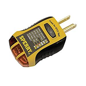
This device works by checking the flow of electricity and the paths it takes even through the ground and neutral connections to ensure all have a good connection and that the connections are made correctly.
If there is a fault, this device will show you precisely where and what the fault is by the indicator lights. Ideally, you should also carry out resistance tests, and trip time tests down to your earth in case of fault but these can vary according to core size and length of cable which also change per house and per state requirements making it hard to go into here but you can check thee through your local electrical suppliers by asking their advice.
Some devices work on battery to test a circuit meaning you can still keep it isolated whereas others require it to be powered back on, so once you are satisfied with the work done you can take off your isolation lock, turn the breaker back on then using your multimeter, you can also check you have your 120 Volts to the right terminal. Once you do and you are completely satisfied with your work then you are safe to use your outlet as normal.
Final Word – Safety First and After
So I always like to add in an afterthought and here it is the emphasis on safety. When doing all DIY jobs, safety is paramount but when working in electrical matters, this really is critical. Not taking proper care and precautions could lead to severe injury at best or at worst be fatal to yourself or other around.
The other concern with electrical work is not the immediate threat of electric shock but what happens is the correct safety checks are not carried out or working procedure followed. This could lead to a dangerous occurrence of short circuits, bad connections and too much resistance in the wires. Eventually, all of these scenarios have the potential for fire, made worse by the fact the cables are hidden away in the wall where you’d never know until the home is ablaze, you begin to see why electrical fires are so hard to spot and then stop once they are going.
With just a few simple safe working practices however and a little or the right knowledge can save you a lot of money, time and even life.
Perhaps one of the most critical practices in any and all electrical work is testing. Both before and after. Now above we have run through a few different, yet critical devices that you’ll need while working, rather than buying each one separate you can go for a cheaper option of buying a multi-equipment package like the one:
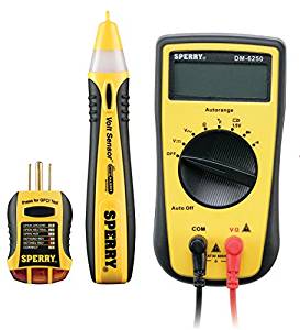
This will save you time and money in the long run as these devices have multiple uses around the house and should be used each and every time you undertake electrical work. Your own and other safety are worth the little bit of extra effort it takes to work safely.
For a visual representation of what we have covered in this article, you can check out the video below.
With jobs like this, your first priority should always be safety first, risking your own life or others is not one we would like to take, especially when so easily avoided with a few simple practices.
Thanks for reading.